To FEC or not to FEC

That is the question I will address here.

Let us assume we are transporting RTCM3.2 MSM 4 over a UHF radio link and we are NOT going to repeat the signal.

With current constellations, tracking to 5 degrees elevation mask, in North America this is about 770 bytes-per-second, most of the time. More on this byte-rate later.

If you have a narrow-banded FCC license, which most of us do, then the only/most universal 9600 baud radio protocol alternative will be:

Satel, 9600, FEC OFF -> 1,100 bytes per second

Satel, 9600, FEC ON -> 830 bytes per second

FEC ON redundantly encodes an error correction code into the stream. So the receiver can detect and fix some bit errors, salvaging a message that would otherwise be destroyed by channel noise.

In a standard communication channel, this makes it so that the receiver does not have to ask to have a damaged message retransmitted. However, in the RTK model, a new RTK message is broadcast every second anyway. So if you miss a message, all you need to do is wait about 1/2 second and a new message will be available. This makes the cost of a missed message effectively zero.

RTCM 3.x Message Types

A typical RTCM3 stream will usually contain four message types:

  • 1004; 1-second; extended L1/L2 RTK Observables, the main message
  • 1006; 30-seconds; RTK Reference Station ARP plus HI, the location of the base
  • 1012; 1-second; GNSS L1/L2 Observables, GNSS main message
  • 1033; 30-seconds; Receiver and antenna information

1006 and 1033 are only important every long-once-in-a-while. Typically they are sent every 15 or 30 seconds so that a receiver need not wait too long to get them when first connected. Turning on a Rover, it will not FLOAT or FIX until it has received a 1006 message, thus if only sent once per minute then you might have to wait an extra minute to get a fix. If you send it every 15-seconds, then a recently turned on receiver would need only wait 15-seconds for the next message. 1004 and 1012 (or perhaps other similar messages) are the typical main payload and are sent every second.

It is probably sufficient for most RTK rovers to get a complete 1004/1012 pair every 5 to 10 seconds with absolutely no loss in accuracy or latency to the RTK result. There may be other main payload message types, but like 1004 and 1012 they only need be received occasionally.

So, what happens if the radio channel is noisy and only one out of 10 messages makes it to the Rover? In general, nothing happens. The rover continues to work just as if it had received every single message. There is no loss of accuracy, no increase in latency and most importantly no increase in HRMS or VRMS.

Number of Tracked SV’s. Maximum Byte Per Second Rates

FEC ON adds 25 to 30% overhead to the original message. Since the message is longer, there may be a higher probability that the message will be damaged in transit. So, a shorter message without FEC may have a higher probability of transfer than a longer message with FEC. But, generally this difference is negated as the longer message with FEC may be correctable.

The real issue is that at times during the day, the total number of tracked SV’s changes and the message which contains corrections for all of the satellites tracked at the base changes in length.

Here is the predicted number of satellites tracked for the CORS station here at my office:

This station is currently sending 770 bytes per second while using (sending corrections) for 37 satellites. (Note: I don’t include QZSS, IRNSS, SBAS SV’s in the correction stream.) Later today I expect that it will sending corrections for 42-satellites and the byte rate will approach 870 bytes per second.

Clearly, 870 bytes per second may be troublesome for a channel that can only support 830 bytes per second (FEC ON). 870 bytes per second will nicely fit into a 1,100 bytes per second stream (FEC OFF).

We often get calls from customers who complain that there rover works great every day until some hour and then the rover starts having issues. It might be that their daily failure is correlated to a time of day when there are usually a very high number of satellites available for tracking. (You can check this by listening to the broadcast frequency, if the radio broadcasts 100% of the time, then too much data.) A reasonable solution to this issue is to raise the elevation mask on the base, which will greatly reduce the number of tracked satellites AND to turn FEC OFF.

RTCM3 vs. SCMRX

If you are working with multiple equipment vendors, then RTCM3 is the safe bet for the most compatible messages. However, if you are working with all ‘mainline’ Trimble receivers then CMRx is a good alternative. If you are working with all OEM Trimble equipment (iG8 and iG9 receivers from iGage for example) then SCMRX (Scrambled CMRX) is a good alternative.

The difference between RTCM3 and SCMRX byte rates for my station using 38 SV’s at this moment is:

RTCM3 MSM4 770 bytes per second

SCMRX 385 bytes per second

So, SCMRX is a lot better choice for the transmitted message type, if all equipment can utilize it.

For a community base, like SGU2, it is not reasonable to broadcast proprietary messages. RTCM3 should be useable by all receivers.

Repeaters

Using a store-and-forward repeater becomes very tricky. Repeaters typically have a 50 ms delay from when they receive the last character of a message until they start retransmitting the message. So the entire message must be transmitted in 475 milliseconds, instead of 1,000 milliseconds. The maximum effective byte rates for FEC ON and OFF is reduced to:

Satel, 9600, FEC OFF -> 495 bytes per second

Satel, 9600, FEC ON -> 394 bytes per second

It is probable that sCMRx, FEC OFF and an elevation mask of 8 degrees may be the only solution that provides 24-7 store-and-forward repeater viability.

But, what if you want to repeat RTCM3 MSM4 signals? Is there possible solution?

I know of two possible work arounds:

  • Use an internet backhaul for the repeater, this makes entire message available to the repeater at the same time as the base, since the TCPIP connection will have very little latency and be relatively fast.
  • Use a dedicated receive only radio to receive the corrections, then send them out a serial port to a dedicated transmit repeater radio for simultaneous transmission. This option requires that the Tx frequency be different than the Rx frequency, the wider the separate the better. Depending on the quality of the IF stages of the dedicated Rx radio and the input/output spacing you might need to add a duplexer, but that would have the benefit of only needed one antenna.

So, summarizing this section: Repeaters are going to be tough going forward with narrow banded radios and high SV counts.

Conclusion

FEC = OFF is the conclusion. If you are using TRANSPARENT at 9600 baud (wideband), same conclusion: FEC OFF.

Leave a comment

Filed under Uncategorized

Let’s raise the level of informed Geodesy in the UAV, GIS … worlds.

We (iGage) sell a lot of GNSS receivers to a variety of markets: survey, engineering, GIS, UAV, agriculture, machine-control, marine, and other interesting uses.

Because we support and service what we sell, I have a lot of interactions with customers who are experiencing failures or difficulties. In talking to them I repeatedly encounter the same reoccurring issues.

Yesterday I talked with a new UAV operator who was bragging about how accurate their results are. The claim is 2 x 3 mm (2 mm horizontal, 3 mm vertical). But, this operator was having some issues with the site control that they set using a static receiver purchased from us.

After talking for a while, I realized that I can’t take this anymore.

Question 1: Do I really have to be polite or can I just tell them to fo and hang up? (I guess we know the answer to this question: I have to be polite.)

Question 2: how can a UAV operator claim to achieve 2 x 3 mm accuracy if they:

  • Don’t know the difference between iFeet (international) and USFeet (Unites States Survey Foot).
  • Have no idea what Grid and Ground distances are.
  • Don’t know what the difference between ‘plate fixed’ and ‘current epoch’ is.
  • Don’t understand the difference between a reference frame and a projection. So they can’t tell You if their data is NAD83xxxx, IGSxx or ITRFxxxx because they don’t understand the difference. Honestly, most claim their data is WGS84 (whatever that might be) when it is actually NAD83 framed. And, I have to ask, does anyone in the USA other than airport operators and the Army want WGS84 framed data? And if someone wants current epoch data, won’t they know and ask for a specific realization? My experience is that anyone who asks for ‘WGS84’ really wants ‘NAD83_xxxx xxxx.xxx’: but they don’t understand that WGS84 is not NAD83, nor do they understand how foolish they appear. If someone really wants current epoch ITRF_xxxx they will ask for it by name, not by some generic, non-specific label like ‘WGS84’.
  • Throw around the term WGS84 but can’t tell you if it is IGS08, ITRF2014 or one of the many other realizations. They scream “I want WGS84!” thinking they are brilliant little UAV geodesists.
  • Have no clue how they might actually convert a current/specific epoch ITRF/IGS coordinate to NAD83xxxx.
  • Can not perform mission planning, in the correct time zone, to determine a best time-of-day for a 15-minute OPUS-RS occupation.
  • Think they can do a 15-minute OPUS-RS occupation and get a 2-mm vertical solution, anywhere in the USA at any time, under any canopy.
  • Don’t have access to NGS OPUS-Projects, so they can not get a more accurate orthometric position on their own: [ see opus-static-a-deep-dive-into-orthometric-height-estimated-errors ]
  • Don’t understand that a relatively accurate ellipsoid height returned by OPUS may not be an equally accurate orthometric height.
  • Don’t understand that selecting different CORS sites to process against will result in different results.
  • Can’t wait for precise ephemeris. Can’t wait for CORS stations that post daily to become available, forcing their 15-minute OPUS-RS solutions to use excessively long baselines to distant CORS.
  • Do not understand the difference between ‘ellipsoid’ and ‘orthometric’ heights, have no idea what a GEOID is, do not understand that the GEOID is NOT a function, but a lookup table. Do not understand that the GEOID is a representation of gravity. Are unaware that water does not necessarily flow downhill in ellipsoid space. Have never transferred an orthometric elevation between two points nor do they have any equipment that would be suitable for this purpose.
  • Have no idea if their GNSS receiver NMEA strings are ellipsoid or orthometric and if orthometric, which GEOID was used to generate them? How to convert an inaccurate NMEA orthometric height to an accurate orthometric height.
  • Have no clue that solid earth tides exist. Have no clue that tidal loading is significant near coastal regions.
  • Don’t understand that the earth is not flat and the curvature is significant over very short distances.
  • Claim to have single digit mm accuracy, but set control and checkpoints with GPS. Sub-centimeter GPS is really tricky. If I was going to claim 1-mm accuracy, I would probably set control with my 1″ robotic total station, not GNSS, right? And all my equipment would be in absolutely top notch condition, cleaned, adjusted and calibrated. But they:
    • Have never adjusted the bubble on their rover pole. (In fact, they have no idea that the bubble is adjustable.)
    • Have not checked the rover pole for runout (is the rod straight?) Spoiler: the rods are NEVER straight. Even new, in the box from the factory the poles have excessive runout.
    • Have never cleaned or adjusted a tripod. (The metal feet literally are loose and rock, the leg hinges are loose, the quick locks on the legs don’t hold. The tripod looks like it has been run in a cement mixer barrel with bags of gravel. The slides are packed with sand and jump when you extend them.)
    • Have never checked the alignment of their tribrach, nor do they have access to an adjusting cylinder. Or a clue how one might check or adjust a tribrach.
    • Don’t own a total station and have never done a field calibration.
    • Use GNSS equipment with non-calibrated antennas. (So the antenna that they are using does not have an NGS relative or IGS absolute calibration.)

I am not going to offer answers to any of these questions today.

My impression is the kids I am talking to have convinced themselves that they are the smartest guys in every room that they walk into. An old guy like me could never help them. But if you read through the items above and don’t definitively understand their points; trust me: you probably should not be offering UAV/GIS services for hire.

Also, at this point I feel the need to disclose that I am not a surveyor, I am not a geodesist, I am no longer even an engineer. I am just a guy who sells survey equipment. And I personally certainly have a lot to learn about geodesy, measurements, coordinates, frames, processing static data, doing adjustments and even more stuff that I don’t even know about. If you read the previous few months of my arcane blog entries, this will be clear.

Oh, one more thing, if you are a UAV operator and you talked to me yesterday, this rant is NOT about you. It is totally about someone else. Totally.

Leave a comment

Filed under Uncategorized

CORS data availability for OPUS processing

We get a lot of complaints about the receivers that we sell when customers submit jobs to NGS OPUS and the solutions are noisy or outright fail.

The answer is always to wait a day or two and resubmit the job. Waiting allows the nearby CORS stations observation data to be posted to the NGS RINEX data repository and subsequently be used to process the seemingly errant job.

I have noticed that most customers don’t like the answer ‘Just wait a day or two and resubmit the job.’ While this is the correct answer, and there is nothing that we can do to change the answer, our customers want more information.

So here you go: [ a deep dive into CORS data availability ] complete with interesting delay estimates like this:

Number of hours after midnight that CORS correction data for P113 becomes available.

Leave a comment

Filed under Uncategorized

A (very, very) deep dive into the computation of Elevation Scale Factors / Ellipsoidal Reduction for GRS80

In my previous blog/FAQ entry I noted that there will be a variety of ESF (Elevation Scale Factors) to be encountered for a given latitude and ellipsoid height.

In this arcane blog entry, I present the NGS Ellipsoid Reduction Method and a deep drive into the resulting differences for various flattening ratio values, compare results obtained with GRS80 vs. WGS84 ellipsoids, look at the scale of errors introduced by using the orthometric height instead of the ellipsoid height and provide links to additional resources.

Keep reading:

Leave a comment

Filed under Uncategorized

Lambert Conformal Conic projections at ground

In keeping with the recent arcane subject series of this blog, I just finished figuring out the details of converting a SPC grid projection (like Utah South NAD83) into a ground system.

This method has the advantage of working in all software packages with a minimum number of system coefficients:

                Origin Lat, Origin Lon, False Northing, False Easting and a single Scale factor

With this method you can exactly duplicate the results you would get from traditional Modified State Plane Projection schemes that involve adding a Combined Scale Factor to a grid system with a single calibration point. While there is nothing wrong with the traditional way, the steps to implement it are different in every field software tool.

With the method that I describe, you just enter a new projection with the five coefficients and you are done.

The short explanation is:

  • Convert the 2-parallel LCC to a single parallel LCC by calculating an equivalent center latitude and the correct scale factor K0
  • Apply the correct ellipsoidial reduction factor with the correct point scale factor for the new projection base point.
  • Compute the correct false northing and easting

While some of the required coefficients are are in the NOS NGS5 SPC manual, I wanted to better understand how they are computed, so I did all the math.

I was surprised by how little information on this subject that I could find on the web, so I wrote a pretty detailed description with a worked example with all of the code that I used. Plus I used the X-PAD field software to validate the results.

If you are interested in this, continue reading this 10-page PDF:

Leave a comment

Filed under Carlson, COORDINATE STUFF, X-PAD

Carlson’s .CRDB Format Notes

The Carlson .CRD format has been around for a long time and it is fairly well documented.

The .CRDB format was released around version 5.04, but really become dependable and useful with the release of 5.06 in August 2017. The ‘new’ .CRDB format expands the size of the point name from 9-characters and the size of the point description from 31-characters to 255 characters each.

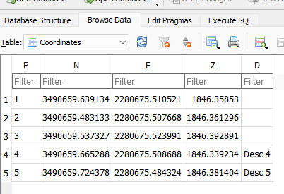
If you change the extension of the .CRDB file from .CRDB to .SQLite, then you can use any standard SQLite client (like ‘DB Browser’: https://sqlitebrowser.org/dl/#windows ) to view the structure:

The structure of a .CRDB (aka .SQLite) file.

and the contents:

Typical contents of a .CRDB file.

I am not sure if point names longer than 9 characters are a good thing and I personally have preferred 4-character point names in the range 0000 to 9999 for years, but I guess I understand STK1024, but extending the descriptions to 255 characters is certainly welcome.

There are also a lot of open source SQLite clients that make reading, writing, sorting, searching, record deletion, db compressing and cleaning for SQLite files very dependable and fast.

I don’t think there any disadvantages to making .CRDB files other than very old versions of SurvCE won’t be able to open them and many 3rd party tools are not .CRDB aware.

3 Comments

Filed under Carlson

X-PAD FAQ’s

I have been writing X-PAD FAQ’s every time I stumble over something interesting. Typically the items are very simple, but I think it is worth writing a bit about them to save others a bit of stumbling. Here is a quick synopsis:

All of the FAQ’s are in a single secure web [ folder ]

Leave a comment

Filed under Uncategorized

What is the best Android tablet for X-PAD?

This entry started out as a link to the Samsung announcement of a new Tab Active tablet in October of 2022. But as usual, I have fallen off topic:

We used to sell data collectors with GNSS receivers. And we still do, however with our switch to X-PAD which runs on ‘basically any Android’ device, it is hard for us to sell data collectors because there are so many and the price points go from $80 to $650 for consumer tablets, all the way up to $3500 for a really nice Juniper Systems Allegro 3 or Mesa 3 data collector.

Which device should you purchase?

There are so many great solutions that it is really hard to make a suggestion. It is easier for me to tell you about the Android devices that I personally have: Pixel 4, Samsung 7, Samsung Tab Active 3. I plan to get a Pixel 7 Pro when they release in October and I am also going to upgrade to the Tab Active 4 when they release ‘any day now’.

Why don’t I have an Allegro 3, Mesa 3 or one of the other super-rugged Android devices? Well, I have gotten used to having the latest version of the Android OS on my phone and Samsung tablets. The Mesa 3 has Android 11 and the Allegro 3 has Android 7.1. The Bluetooth 5.x on the Pixel/Samsung seems to go 2 to 4 times further than the Bluetooth on these devices. The screen on the Tab Active has a lot finer detail. The new devices have full banded 5G modems, while slightly older devices have band limited 4G modems.

But the big difference is cost. The Tab Active 3 is $560 on Amazon with overnight delivery in Salt Lake City. That is 6.25 times less than a similar super rugged device!

Cell Phone vs. Tablet

I find that I use my cell phone 95% of the time. I use it for demos, I use it for support, I use it to test receivers and I use it for most survey related functions. If a customer calls me on my cell phone and I am talking on it, then I use my tablet to help with support. If I was doing construction layout or using the volume tools in X-PAD then I would use my tablet because it has a bigger, screen. But I don’t do construction layout or volume work.

The best data collector for me is the one that is always in my pocket.

Things to consider

Removable batteries. Time to charge: if device will charge from 20% to 80% in 20-minutes, then that is something. External charger for 2nd battery available?

Android OS Version.

Camera resolution and picture quality. Pixel and Samsung seem to have great image processing and I take a lot of pictures of cut stones. Will the Auto Focus quickly focus on a cut stone or brass cap?

Bluetooth version (5.x has much better range!)

Network Modem: 4G or 5G LTE? Verizon network compatibility? Network sensitivity. e-SIM?

Sufficient 4G/5G bands? Consider the difference between these two devices:

LTE: 2, 4, 5, 12, EU 1, 3, 7, 8, 20, 28, and AU 1, 3, 5, 7, 8, 28

and

#2: LTE: B1/2/3/4/5/7/8/12/13/14/17/18/19/20/25/26/28/29/30/38/39/40/41/42/48/66/71
5G Sub-610: Bands n1/2/3/5/7/8/12/20/25/28/30/38/40/41/48/66/71/77/78

The second device sure looks better!

Wi-Fi compatibility: Wi-Fi 6 (802.11 a/b/g/n/ac/ax, 2.4GHz + 5GHz, MIMO) or something else?

Rugged case availability. Mounting options for poles and ATV’s. Stylus compatibility.

Fast enough CPU speed? SD card slot for memory expansion (in case you want to put all the BLM field notes in PDF format on your device.)

Screen bright enough? Sunlight tolerance: most of these devices just turn off when they get hot. Screen resolution, not just size may be important for you.

What IP rating? (IP68 is probably best.) Which Gorilla(r) glass? (5 is good.)

I like a fingerprint reader for quick login. And since my devices are connected to my personal google accounts, I want them locked if I leave them around.

Operating temperature range? This may not be important for me because my personal operating range is so narrow.

Do you need a built in serial port?

Conclusion

Which device should you purchase? What ever makes you the happiest might be best.

I am really looking forward to a big new Pixel phone and will be excited to have a Tab Active 4 too!

Leave a comment

Filed under Uncategorized

OPUS-Static: a deep dive into orthometric height estimated errors

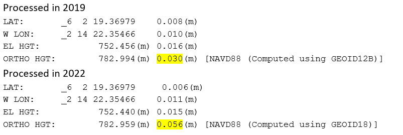
A few years ago (perhaps 2019) the NGS changed the way that they computed the estimated orthometric peak-to-peak errors reported on an OPUS report.

Previously three items:

  • observed peak-to-peak ellipsoid value
  • estimated error for the geoid
  • and (perhaps) a county wide adder

combined to build an estimated error. The new method combines the observation duration, peak-to-peak ellipsoid observation, the estimated geoid error and the solution’s RMS error:

You would be correct to assume that nearly all occupations reprocessed using this new method will report higher estimated errors.

Here is an actual example, with the location obfuscated:

I made a simple spreadsheet to compute estimated errors using the new NGS method:

Here is a link to the Excel spreadsheet:

With a data table, we can look at the results of shorter and longer occupations:

It should come as no surprise that, all other things equal, even a 48-hour occupation will not match the 3cm result from 2019.

Before I suggest a solution to this higher orthometric estimated error ‘problem’, lets take a moment to compare some of the contributions other than time to the orthometric estimated error.

Baseline (distance) from CORS to your observation

When you process an OPUS observation soon after the observation completes, the nearest available CORS stations may be a long ways distant. In the example above, in 2022 after waiting 3-years to process, every possible CORS station will have posted data and the data will have been Quality Checked by the NGS. Bad stations will have been mapped out.

Closer CORS stations will typically have better matching ellipsoid elevations which in turn will reduce the reported orthometric error.

Good and Bad CORS

There are good CORS stations and bad CORS stations that suck. There are many reasons that make stations inferior:

  • nearby buildings or canopy
  • non chokering antennas
  • antennas without matching absolute calibrations (unlisted domes)
  • bad or insanely long antenna cables on the CORS stations
  • old CORS station firmware
  • poor mechanical mounts
  • … and many more …

OPUS (generally speaking) assumes that all CORS stations are perfect. Even if they are not. So if a station has a bad position, or has extreme multipath, then OPUS does not throw the station away. OPUS assumes the station is perfect and that all of the errors are the fault of your observation.

You should look at the short-term plots for the stations in a solution and exclude stations that suck.

Rapid vs. Precise vs. Final Orbits

While the ephemeris that are used in the OPUS solution don’t matter nearly as much as they used to, you may get a cleaner solution by waiting for precise orbits to become available, usually 15-days after the end of your observation.

Geoid accuracy

For the example above, the original solution was computed with GEOID 12B:

And the second solution used GEOID18:

The estimated error for GEOID18 is 1cm better than GEOID12B. But as you have seen, this does not translate into a smaller orthometric error estimate.

Solution: getting a lower error estimate

If your original occupation spanned longer than 4-hours, it will be possible to break it half and submit each half as a separate session into an OPUS-Project project.

While it would certainly be better to collect the raw observations on two separate days; or do morning/evening splits, with disparate physical setups; splitting the observation into two 2-hour or longer sessions will work.

Here are the results of the OPUS Project using all default settings:

with a 2.2 cm orthometric error estimate.

So, while the new OPUS-Static computation method for orthometric height estimated error may not get you where you want to be, OPUS-Projects probably will.

1 Comment

Filed under OPUS, Uncategorized

SurvCE/SurvPC: FAQ Single or Multi-Point Localizations at Ground

Step-by-step instructions for setting up a ground system for a single point or multiple points linked below:

Single Point:

Two-Point Arbitrary Bearing:

Leave a comment

Filed under Uncategorized